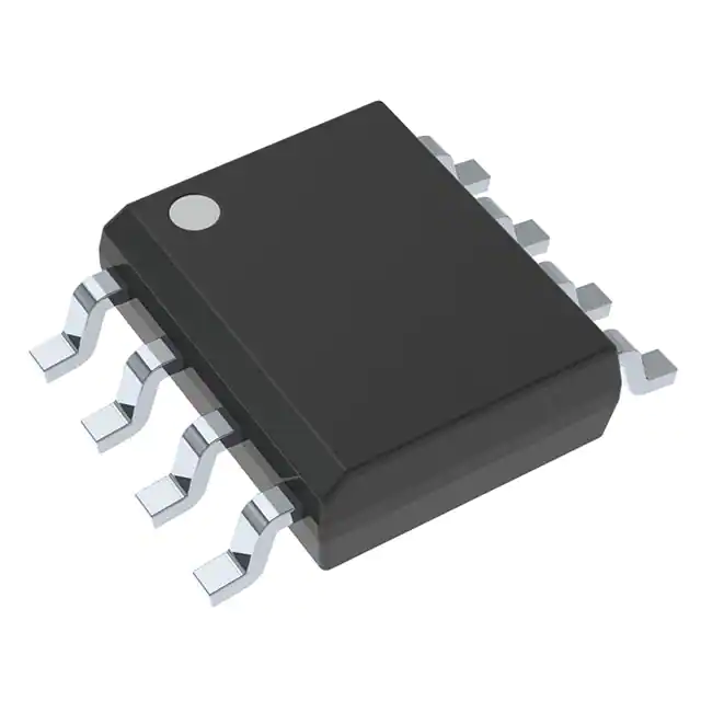
TCAN1042HGVDRQ1 SOP8 Electronic Components Distribution New Original Tested Integrated Circuit Chip IC TCAN1042HGVDRQ1
Product Attributes
| TYPE | DESCRIPTION |
| Category | Integrated Circuits (ICs) |
| Mfr | Texas Instruments |
| Series | Automotive, AEC-Q100 |
| Package | Tape & Reel (TR)
Cut Tape (CT) Digi-Reel® |
| SPQ | 2500 T&R |
| Product Status | Active |
| Type | Transceiver |
| Protocol | CANbus |
| Number of Drivers/Receivers | 1/1 |
| Duplex | - |
| Receiver Hysteresis | 120 mV |
| Data Rate | 5Mbps |
| Voltage - Supply | 4.5V ~ 5.5V |
| Operating Temperature | -55°C ~ 125°C |
| Mounting Type | Surface Mount |
| Package / Case | 8-SOIC (0.154", 3.90mm Width) |
| Supplier Device Package | 8-SOIC |
| Base Product Number | TCAN1042 |
1.
PHY is a rising star in in-vehicle applications (such as T-BOX) for high-speed signal transmission, while CAN is still an indispensable member for lower-speed signal transmission. The T-BOX of the future will most likely need to display vehicle ID, fuel consumption, mileage, trajectory, vehicle condition (door and window lights, oil, water and electricity, idle speed, etc.), speed, location, vehicle attributes, vehicle configuration, etc. on the car network and mobile car network, and these relatively low-speed data transmission is relying on the main character of this article, CAN.
The CAN bus was introduced by Bosch in Germany in the 1980s and has since become an integral and important part of the car. To meet the different requirements of in-vehicle systems, the CAN bus is divided into high-speed CAN and low-speed CAN. high-speed CAN is mainly used for the control of power systems that require high real-time performance, such as engines, automatic transmissions, and instrument clusters. Low-speed CAN is mainly used for the control of comfort systems and body systems that require less real-time performance, such as air conditioning control, seat adjustment, window lifting, and so on. In this article, we will focus on high-speed CAN.
Although CAN is a very mature technology, it still faces challenges in automotive applications. In this paper, we will look at some of the challenges CAN is facing and introduce the relevant technologies to address them. Finally, the advantages of TI's CAN applications and its rather "hardcore" products will be described in detail.
2.
Challenge one: EMI performance optimization
As the density of electronics in vehicles increases each year, the electromagnetic compatibility (EMC) of in-vehicle networks is being demanded even more, because when all components are integrated into the same system, it is essential to ensure that the subsystems work as expected, even in the face of noisy environments. One of the major challenges faced by CAN is the exceedance of conducted emissions caused by common mode noise.
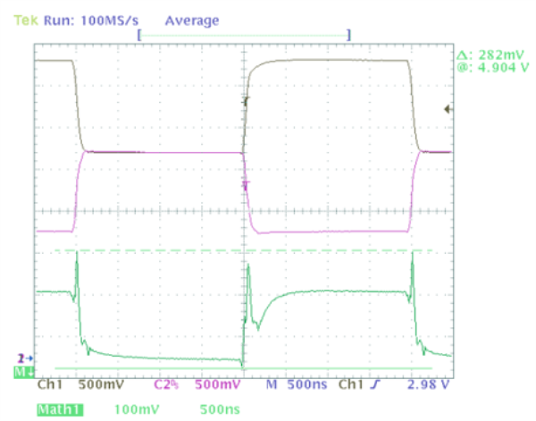
Ideally, CAN uses differential link transmission to prevent external noise coupling. In practice, however, CAN transceivers are not ideal and even a very slight asymmetry between CANH and CANL can produce a corresponding differential signal, which causes the common mode component of CAN (i.e. the average of CANH and CANL) to cease to be a constant DC component and become data-dependent noise. There are two types of imbalance that result in this noise: low-frequency noise caused by a mismatch between the steady state common mode level in the dominant and recessive states, which has a wide frequency range of noise patterns and appears as a series of uniformly spaced discrete spectral lines; and high-frequency noise caused by the time difference between the transition between dominant and recessive CANH and CANL, which consists of short pulses and disturbances generated by data edge jumps. Figure 1 below shows an example of typical CAN transceiver output common mode noise. Black (channel 1) is CANH, purple (channel 2) is CANL and green indicates the sum of CANH and CANL, the value of which is equal to twice the common mode voltage at a given point in time.
.png)