


New and Original in TCAN1042VDRQ1 Electronic Components Integrated Circuit Ics Origin 1- 7 Working One Stop BOM List Service

Product Attributes
| TYPE | DESCRIPTION |
| Category | Integrated Circuits (ICs) |
| Mfr | Texas Instruments |
| Series | Automotive, AEC-Q100 |
| Package | Tape & Reel (TR)
Cut Tape (CT) Digi-Reel® |
| SPQ | 2500 T&R |
| Product Status | Active |
| Type | Transceiver |
| Protocol | CANbus |
| Number of Drivers/Receivers | 1/1 |
| Duplex | - |
| Data Rate | 5Mbps |
| Voltage - Supply | 4.5V ~ 5.5V |
| Operating Temperature | -55°C ~ 125°C |
| Mounting Type | Surface Mount |
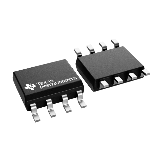
| Package / Case | 8-SOIC (0.154", 3.90mm Width) |
| Supplier Device Package | 8-SOIC |
| Base Product Number | TCAN1042 |
This CAN transceiver family is compliant with the ISO 1189-2 (2016) high-speed CAN (Controller Area Network) physical layer standard. All devices are designed for use in CAN FD networks with data rates up to 2Mbps (megabits per second). Devices with a "G" suffix are designed for CAN FD networks with data rates up to 5Mbps, and devices with a "V" suffix have an auxiliary power input for I/O level conversion (to set the input pin threshold and RDX output level). The series features a low-power standby mode and remote wake-up requests. In addition, all devices include a number of protection features to improve device and CAN stability.
This CAN transceiver family is compliant with the ISO 1189-2 (2016) high-speed CAN (Controller Local Area Network) physical layer standard. All devices are designed for use in CAN FD networks with data rates up to 2Mbps (megabits per second). Devices with a "G" suffix are designed for CAN FD networks with data rates up to 5Mbps, and devices with a "V" suffix have an auxiliary power input for I/O level conversion (to set the input pin threshold and RDX output level). The series features a low-power standby mode and remote wake-up requests. In addition, all devices include a number of protection features to improve the stability of the device and the CAN.
What is a CAN transceiver?
A CAN transceiver is a 232- or 485-like converter chip whose main function is to convert the TTL signal of the CAN controller into a differential signal of the CAN bus.
What CAN controller TTL signals?
Today's CAN controllers are generally integrated with the MCU and their transmit and receive TTL signals are the MCU pin (high or low) signals.
Previously there were separate CAN controllers and a CAN network node would contain three chips: MCU chip, CAN controller, and CAN transceiver. Now it is the first two that are integrated together (see picture at the beginning of the article).
Input characteristics
For isolated CAN transceivers, the input refers mainly to the input characteristics on the CAN controller side of the connection, comprising the power input and the signal input.
Depending on the CAN interface voltage of the controller a 3.3V or 5V powered CAN module can be selected. The normal input range of the isolated CAN module is VCC ±5%, mainly considering that the CAN bus level can be kept within the typical value range and also making the secondary CAN chip work around the nominal supply voltage.
For separate CAN transceiver chips, the VIO pin of the chip needs to be connected to the same reference voltage as the TXD signal level to match the signal level, or if there is no VIO pin, the signal level should be kept in line with VCC. When using CTM series isolated transceivers it is necessary to match the signal level of TXD with the supply voltage, i.e. 3.3V standard CAN controller interface or 5V standard CAN controller interface.
Transmission characteristics
The transmission characteristics of a CAN transceiver are based on three parameters: transmit delay, receive delay, and cycle delay.
When choosing a CAN transceiver we assume that the smaller the delay parameter the better, but what benefits does a small transmission delay bring and what factors limit the transmission delay in a CAN network?
In the CAN protocol, the sending node sends data via TXD while RDX monitors the bus state. If the RDX monitor bit does not match the transmit bit, the node detects a bit of error. If what is monitored in the arbitration field does not match the actual transmission, the node stops transmitting, i.e. there are multiple nodes on the bus sending data at the same time and the node is not given data transmission priority.
Similarly, in both the data check and ACK response bits, the RDX is required to obtain the data status of the bus in real-time. For example, in normal network communication, excluding node abnormalities, in order to reliably receive the ACK response, it is necessary to ensure that the ACK bit is transferred to the RDX register of the controller within a certain time, otherwise, the sending node will detect an answer error. Set the sampling position to 70% at 1Mbps. Then the controller will sample the ACK bit at 70% of the time point from the start of the ACK bit time, i.e. the cycle delay of the entire CAN network has to be less than 700ns, from the time the TXD sends, until the ACK bit is received at the RDX.
In an isolated CAN network, this parameter is mainly determined by the isolator delay, the CAN driver delay, and the cable length. A small delay time, therefore, helps to sample the ACK bits reliably and to increase the bus length. Figure 2 shows the ACK response of two nodes communicating using the CTM1051KAT transceiver. The typical delay time inherent to the transceiver is approximately 120ns.
-

Brand new genuine original IC stock Electronic ...
-

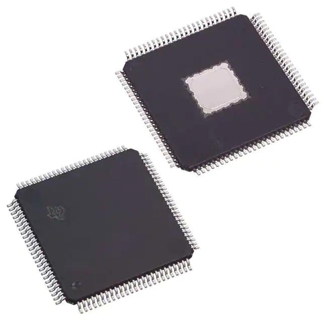
TMS320F28035PNT Microcontrollers IC Chip MUC 32...
-
SEESEND original and new integrated circuits el...
-
Original New In Stock MOSFET Transistor Diode T...
-
TMS320F28069PZPS Good Price IC Chip Original El...
-
5M240ZT100C5N Integrated Circuits New original ...