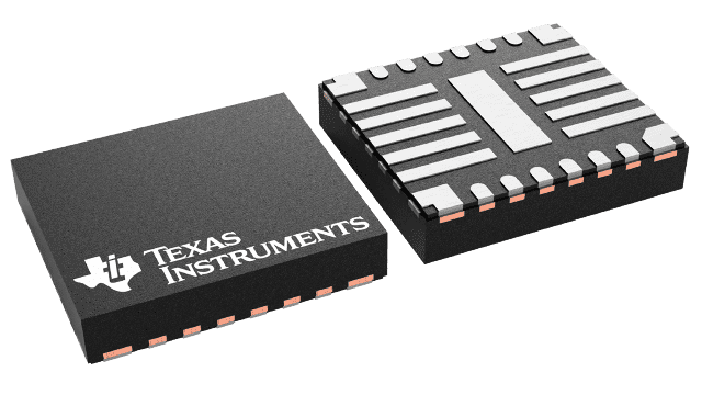
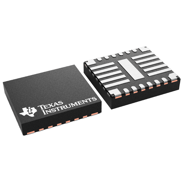
LP87524BRNFRQ1 VQFN-HR26 Components New Original Tested Integrated Circuit Chip IC LP87524BRNFRQ1
.jpg)
Product Attributes
| TYPE | DESCRIPTION |
| Category | Integrated Circuits (ICs) |
| Mfr | Texas Instruments |
| Series | Automotive, AEC-Q100 |
| Package | Tape & Reel (TR)
Cut Tape (CT) Digi-Reel® |
| SPQ | 3000 T&R |
| Product Status | Active |
| Function | Step-Down |
| Output Configuration | Positive |
| Topology | Buck |
| Output Type | Programmable |
| Number of Outputs | 4 |
| Voltage - Input (Min) | 2.8V |
| Voltage - Input (Max) | 5.5V |
| Voltage - Output (Min/Fixed) | 0.6V |
| Voltage - Output (Max) | 3.36V |
| Current - Output | 4A |
| Frequency - Switching | 4MHz |
| Synchronous Rectifier | Yes |
| Operating Temperature | -40°C ~ 125°C (TA) |
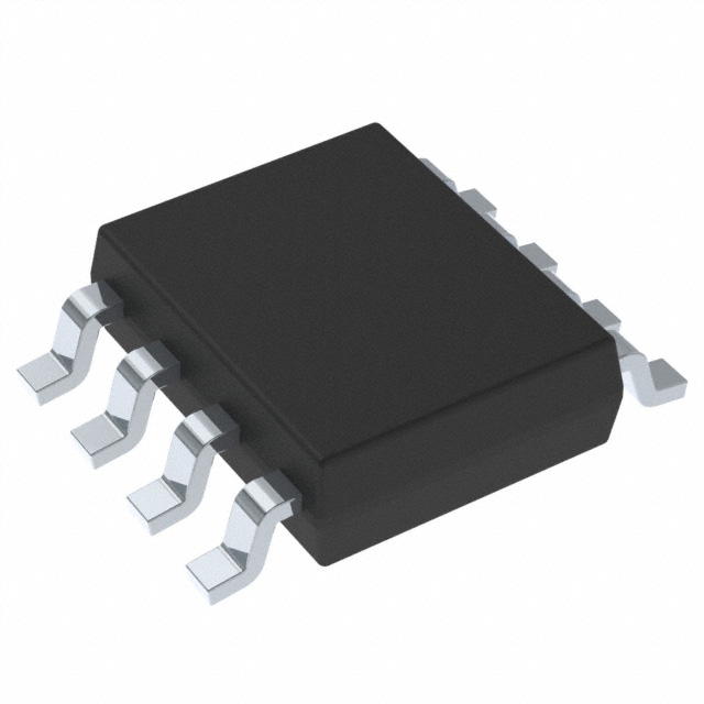
| Mounting Type | Surface Mount, Wettable Flank |
| Package / Case | 26-PowerVFQFN |
| Supplier Device Package | 26-VQFN-HR (4.5x4) |
| Base Product Number | LP87524 |
1.
The function of a converter
A converter is a device that converts a signal into another signal. A signal is a form or carrier of information that exists, and in automatic instrumentation equipment and automatic control systems, a signal is often converted into another signal that is compared with a standard or reference quantity to link the two types of instrumentation together, so the converter is often the intermediate link between two instruments (or devices).
2.
How to buck converters work
A buck converter is a switch mode power supply, a class of device that contains a switch (usually a MOSFET) to quickly turn the circuit on and off, this fast switching produces a square wave, if the duty cycle of the switch is set to 50%, i.e. the switch is on 50% of the time, the average voltage will be 50% of the input.
The square wave needs to be smoothed to provide useful power and often inductors and capacitors are used in series to achieve this function. This combination is known as an LC low-pass filter, where the characteristics of the inductor smooth out the current and the capacitor resists sudden changes in voltage. The combined effect produces a relatively smooth voltage output with a low ripple. For example, if the input voltage is 10V and the switch uses a 50% duty cycle, the output voltage will be 5V.
Another necessary component of a buck converter is a diode or other switch connected in parallel with an inductor. This is to compensate for the function of the inductor, where the current in the inductor cannot be changed instantaneously, protecting the switching tubes from damage by overload.
The buck converter also contains additional circuitry to ensure a stable output voltage. The converter uses a closed-loop control scheme with negative feedback to monitor the voltage output and dynamically adjust the duty cycle of the switches to regulate the output voltage.
3.
Design considerations for buck converters
buck converters are very efficient, with some devices achieving efficiencies in excess of 95%.
buck converters are more cost-effective than linear regulators at high power levels, where the cooling cost of a linear regulator may be less than the cost of using a buck converter
the output of a buck converter contains noise, which means that the output of a linear regulator is more stable and better suited to applications requiring low output noise
linear regulators can respond quickly to input and output changes compared to buck converters.