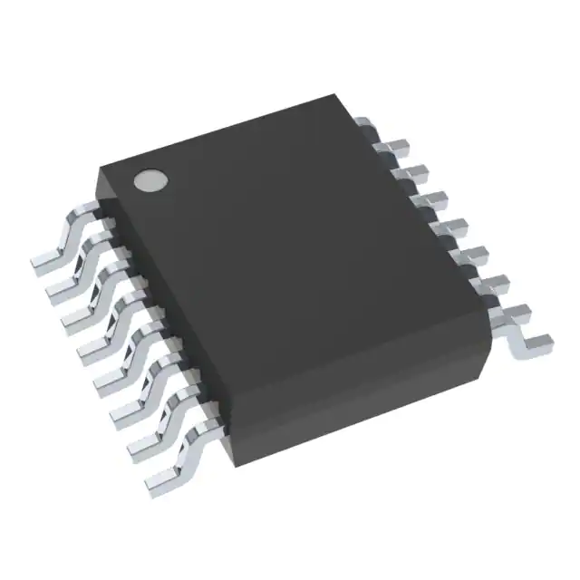
LM46001AQPWPRQ1 HTSSOP Components New&Original Tested Integrated Circuit IC Chips Electronics
Product Attributes
|
TYPE |
DESCRIPTION |
|
Category |
Integrated Circuits (ICs) PMIC - Voltage Regulators - DC DC Switching Regulators |
|
Mfr |
Texas Instruments |
|
Series |
Automotive, AEC-Q100, SIMPLE SWITCHER® |
|
Package |
Tape & Reel (TR) Cut Tape (CT) Digi-Reel® |
|
SPQ |
250T&R |
|
Product Status |
Active |
|
Function |
Step-Down |
|
Output Configuration |
Positive |
|
Topology |
Buck |
|
Output Type |
Adjustable |
|
Number of Outputs |
1 |
|
Voltage - Input (Min) |
3.5V |
|
Voltage - Input (Max) |
60V |
|
Voltage - Output (Min/Fixed) |
1V |
|
Voltage - Output (Max) |
28V |
|
Current - Output |
1A |
|
Frequency - Switching |
200kHz ~ 2.2MHz |
|
Synchronous Rectifier |
Yes |
|
Operating Temperature |
-40°C ~ 125°C (TJ) |
|
Mounting Type |
Surface Mount |
|
Package / Case |
16-TSSOP (0.173", 4.40mm Width) Exposed Pad |
|
Supplier Device Package |
16-HTSSOP |
|
Base Product Number |
LM46001 |
Advantages
Comparison of the advantages of integrated switches and external switches for buck converters
1. External versus integrated switches.
There are several integrated switches and external switches in buck converter solutions, the latter often referred to as step-down or buck controllers. These two types of the switch have distinct advantages and disadvantages and therefore the choice between them must be made with their respective advantages and disadvantages in mind.
Many integrated switches have the advantage of having a low component count, an advantage that allows these switches to have a small size and be used in many low-current applications. Due to their integrated nature, they all exhibit good EMI performance while being protected against high temperatures or other external influences that may occur. However, they also have the disadvantage of current and thermal limits; whereas external switches offer greater flexibility, with current handling capability limited only by the choice of external FETs. On the negative side, external switches require more components and must be protected from potential problems.
To handle higher currents, the switches also have to be larger, which makes integration more expensive as it takes up more valuable space on the chip and requires a larger package. Power consumption is also a challenge. Therefore, we can conclude that for higher output currents (usually above 5A), external switches are the preferred choice.
2. Synchronous versus asynchronous rectification
An asynchronous or non-synchronous rectifier buck converter with only one switch requires a continuity diode in the low path, whereas in a synchronous rectifier buck converter with two switches the second switch replaces the above-mentioned continuity diode. Compared to synchronous solutions, asynchronous rectifiers have the advantage of providing a cheaper solution, but their efficiency is not very high.
Using a synchronous rectifier topology and connecting an external Schottky diode in parallel with the low-level switch will give the highest efficiency. The higher complexity of this low-level switch increases the efficiency due to the presence of a lower voltage drop in the "on" state compared to the Schottky diode. During the stall time (when both switches are off), the external Schottky diode has a lower dropout performance compared to the internal back gate diode of the FET.
3. External vs. internal compensation
In general, buck controllers with external switches can provide external compensation as they are suitable for a wide range of applications. External compensation helps to adapt the control loop to various external components such as FETs, inductors, and output capacitors.
For converters with integrated switches, both external and internal compensation are typically used. Internal compensation enables very fast process validation cycles and small PCB solution sizes.
The advantages of internal compensation can be summarised as ease of use (as only the output filter needs to be configured), fast design, and a small number of components, thus providing a small-size solution for low current applications. The disadvantages are that they are less flexible and the output filter must be subordinated to internal compensation. External compensation offers greater flexibility and can be adjusted according to the selected output filter, while the compensation can be a smaller solution for larger currents, but this application is more difficult.
4. Current-mode control versus voltage-mode control
The regulator itself can be controlled in either voltage mode or current mode. In voltage mode control, the output voltage provides primary feedback to the control loop, and feedforward compensation is usually implemented by using the input voltage as a secondary control loop to enhance transient response behavior; in current mode control, the current provides primary feedback to the control loop. Depending on the control loop, this current can be the input current, the inductor current, or the output current. The secondary control loop is the output voltage.
Current mode control has the advantage of providing a fast feedback loop response, but requires slope compensation, switching noise filtering for current measurement, and power losses in the current detection loop. Voltage mode control does not require slope compensation and provides a fast feedback loop response with feedforward compensation, although the transient response is recommended here to enhance performance, the error amplification circuit may require higher bandwidth.
Both current and voltage mode control topologies are suitable for tuning to be used in most applications. In many cases, current-mode control topologies require an additional current loop detection resistor; voltage-mode topologies with integrated feed-forward compensation achieve almost identical feedback loop response and do not require a current loop detection resistor. In addition, feed-forward compensation simplifies compensation design. Many single-phase developments have been realized using voltage-mode control topologies.
5. Switches, MOSFETs and MOSFETs
The switches in common use today are enhanced MOSFETs and there are many step-down/step-down converters and controllers that use MOSFETs and PMOSFET drivers. MOSFETs typically offer more cost-effective performance than MOSFETs and the driver circuitry on this device is more complex. To switch an NMOSFET on and off, a higher gate voltage than the input voltage of the device is required. Technologies such as bootstrapping or charge pumps must be integrated, increasing the cost and reducing the initial cost advantage of MOSFETs.
About Product
The LM46001-Q1 regulator is an easy-to-use synchronous step-down DC-DC converter capable of driving up to 1 A of load current from an input voltage ranging from 3.5 V to 60 V. The LM46001-Q1 provides exceptional efficiency, output accuracy and drop-out voltage in a very small solution size. An extended family is available in 0.5-A and 2-A load current options in pin-to-pin compatible packages. Peak current mode control is employed to achieve simple control loop compensation and cycle-by-cycle current limiting. Optional features such as programmable switching frequency, synchronization, power-good flag, precision enable, internal soft start, extendable soft start, and tracking provide a flexible and easy-to-use platform for a wide range of applications. Discontinuous conduction and automatic frequency reduction at light loads improve light load efficiency. The family requires few external components and pin arrangement allows simple, optimum PCB layout. Protection features include thermal shutdown, VCC undervoltage lockout, cycle-by-cycle current limit, and output short-circuit protection. The LM46001-Q1 device is available in the 16-pin HTSSOP (PWP) package (6.6 mm × 5.1 mm × 1.2 mm) with 0.65-mm lead pitch. The device is pin-to-pin compatible with LM4360x and LM4600x families. The LM46001A-Q1 version is optimized for PFM operation and recommended for new designs.