One stop service 2022+ in-stock Original&New IC CHIPS Electronics Components LM25118Q1MH/NOPB
Product Attributes
|
TYPE |
DESCRIPTION |
|
Category |
Integrated Circuits (ICs) PMIC - Voltage Regulators - DC DC Switching Controllers |
|
Mfr |
Texas Instruments |
|
Series |
Automotive, AEC-Q100 |
|
Package |
Tube |
|
SPQ |
73Tube |
|
Product Status |
Active |
|
Output Type |
Transistor Driver |
|
Function |
Step-Up, Step-Down |
|
Output Configuration |
Positive |
|
Topology |
Buck, Boost |
|
Number of Outputs |
1 |
|
Output Phases |
1 |
|
Voltage - Supply (Vcc/Vdd) |
3V ~ 42V |
|
Frequency - Switching |
Up to 500kHz |
|
Duty Cycle (Max) |
75% |
|
Synchronous Rectifier |
No |
|
Clock Sync |
Yes |
|
Serial Interfaces |
- |
|
Control Features |
Enable, Frequency Control, Ramp, Soft Start |
|
Operating Temperature |
-40°C ~ 125°C (TJ) |
|
Mounting Type |
Surface Mount |
|
Package / Case |
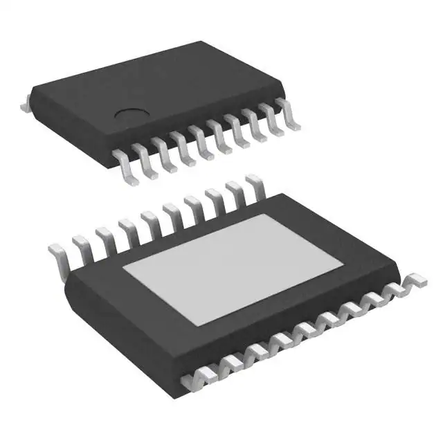
20-PowerTSSOP (0.173", 4.40mm Width) |
|
Supplier Device Package |
20-HTSSOP |
|
Base Product Number |
LM25118 |
Difference
A. What is the difference between a voltage regulator and a booster?
Voltage regulators and boosters, in principle, voltage regulators and boosters are not much different, and voltage regulators and boosters in function and use, voltage regulators and boosters have great difference.
Voltage regulator is mainly used for voltage instability, and voltage fluctuations are relatively large, its voltage fluctuations can not meet the normal use of electrical equipment requirements, and voltage regulator, is the fluctuation of the larger, the voltage stabilization, the voltage stability in a certain range of values, to ensure that electrical equipment can work normally.
The voltage regulator in the process of operation, there will be too low voltage as well as too high voltage, when the voltage is too low, the voltage regulator will be over the voltage line boost work, when the voltage is too high, the voltage regulator is the voltage for the buck work. To ensure that the voltage is smooth. So the voltage regulator that can be boosted, can also be a buck.
Boosters, from the name we can see the use of the product, that is, the voltage to boost the set of equipment, and this equipment only provides voltage boosting work. And is to provide a fixed boost value, such as booster boost value is 100V, when the voltage from 300V to 400V, the output voltage of the booster will also be from 400V to 500V, booster in the use of the process, can only enhance the voltage, but can not stabilize the voltage, so the booster is generally used in places where the voltage is relatively stable. If in the environment of frequent voltage fluctuations, the output voltage is also fluctuating.
In fact, boosters and voltage regulators to compare, because the function of the two can not, the use is not used, so both can not do a comparison, and can not judge who is better and who is worse, which needs to be judged because of the environment. Using the right equipment can play a role, if the wrong use, then the equipment will not work.
Although the two can not be judged good or bad, if we are not sure whether to use the booster or voltage regulator, if we have sufficient funds for the budget, we can directly choose the voltage regulator. This is because the voltage regulator is perfectly suited to the requirements of the booster and the nature of the booster's work, in terms of its use and performance. Due to the different environments and uses, the regulator and booster can not be compared, so we can not say who is good and who is bad.
B.What is meant by synchronous rectification? What is the difference between synchronous and non-synchronous?
The usual rectification is the use of the diode's single conductor characteristics to rectify the current, the rectification process does not require human control. Because the current forward, reverse cut-off, but because the diode itself will have current through the voltage drop, the rectification process will lose energy, resulting in heat, and the power conversion efficiency of this rectification stage will be pulled down.
Synchronous rectification means that instead of using a diode in the rectification section, an MOS is used instead. Because the MOS conducts with very little resistance, the heat generation is minimal energy is lost, so the power conversion efficiency is increased. The synchronous rectification process is such that when energy transfer from the primary side to the secondary side is required, the corresponding MOS tube on the secondary side opens and allows current to flow through. Conversely, when the energy transfer is not required, the MOS tube is switched off, preventing the current from flowing.
To illustrate, in a flyback, when the main switching tube is switched off, the synchronous rectifier MOS tube on the secondary side is switched on, allowing current to flow. When the main switching tube is opened, the synchronous rectifier MOS is switched off to stop the current from flowing through and the transformer stores the energy. In the synchronous finishing process, it is necessary to control the on and off times of the two MOS parts, alternately opening and closing them to form a synchronous rectifier, so it is called synchronous rectification. The process is more complex compared to diode rectification.
About Product
The LM25118-Q1 wide voltage range Buck-Boost switching regulator controller features all of the functions necessary to implement a high-performance, cost-efficient Buck-Boost regulator using a minimum of external components. The Buck-Boost topology maintains output voltage regulation when the input voltage is either less than or greater than the output voltage making it especially suitable for automotive applications. The LM25118 operates as a buck regulator while the input voltage is sufficiently greater than the regulated output voltage and gradually transitions to the buck-boost mode as the input voltage approaches the output. This dual-mode approach maintains regulation over a wide range of input voltages with optimal conversion efficiency in the buck mode and a glitch-free output during mode transitions. This easy-to-use controller includes drivers for the high-side buck MOSFET and the low-side boost MOSFET. The control method of the regulator is based upon current mode control using an emulated current ramp. Emulated current mode control reduces noise sensitivity of the pulse-width modulation circuit, allowing reliable control of the very small duty cycles necessary in high input voltage applications. Additional protection features include current limit, thermal shutdown, and an enable input. The device is available in a power-enhanced, 20-pin HTSSOP package featuring an exposed die attach pad to aid thermal dissipation.