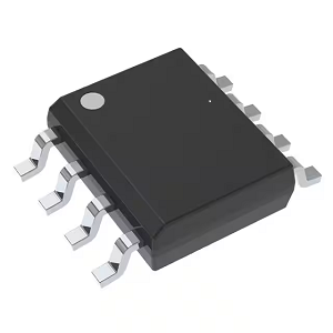
3-A Synchronous Step-Down Voltage Converter Integrated circuit IC LMR33630BQRNXRQ1
.jpg)

Product Attributes
| TYPE | DESCRIPTION |
| Category | Integrated Circuits (ICs) |
| Mfr | Texas Instruments |
| Series | Automotive, AEC-Q100 |
| Package | Tape & Reel (TR) |
| SPQ | 3000 T&R |
| Product Status | Active |
| Function | Step-Down |
| Output Configuration | Positive |
| Topology | Buck |
| Output Type | Adjustable |
| Number of Outputs | 1 |
| Voltage - Input (Min) | 3.8V |
| Voltage - Input (Max) | 36V |
| Voltage - Output (Min/Fixed) | 1V |
| Voltage - Output (Max) | 24V |
| Current - Output | 3A |
| Frequency - Switching | 1.4MHz |
| Synchronous Rectifier | Yes |
| Operating Temperature | -40°C ~ 125°C (TJ) |
| Mounting Type | Surface Mount, Wettable Flank |
| Package / Case | 12-VFQFN |
| Supplier Device Package | 12-VQFN-HR (3x2) |
| Base Product Number | LMR33630 |
1.
The function of a buck converter is to reduce the input voltage and match it to the load. The basic topology of a buck converter consists of the main switch and a diode switch used during the break. When a MOSFET is connected in parallel with a continuity diode, it is called a synchronous buck converter. The efficiency of this buck converter layout is higher than that of past buck converters due to the parallel connection of the low-side MOSFET with the Schottky diode. Figure 1 shows a schematic of a synchronous buck converter, which is the most common layout used in desktop and notebook computers today.
2.
Basic calculation method
The transistor switches Q1 and Q2 are both N-channel power MOSFETs. these two MOSFETs are usually referred to as high-side or low-side switches and the low-side MOSFET is connected in parallel with a Schottky diode. These two MOSFETs and the diode form the main power channel of the converter. The losses in these components are also an important part of the total losses. The size of the output LC filter can be determined by the ripple current and ripple voltage. Depending on the particular PWM used in each case, the feedback resistor networks R1 and R2 can be selected and some devices have a logic setting function for setting the output voltage. The PWM has to be selected according to the power level and the operating performance at the desired frequency, which means that when the frequency is increased, there needs to be sufficient drive capability to drive the MOSFET gates, which constitute the minimum number of components required for a standard synchronous buck converter.
The designer should first check the requirements, i.e. V input, V output and I output as well as the operating temperature requirements. These basic requirements are then combined with the power flow, frequency, and physical size requirements that have been obtained.
3.
The role of buck-boost topologies
Buck-boost topologies are practical because the input voltage can be smaller, larger, or the same as the output voltage while requiring an output power greater than 50 W. For output powers less than 50 W, the single-ended primary inductor converter (SEPIC) is a more cost-effective option as it uses fewer components.
Buck-boost converters operate in buck mode when the input voltage is greater than the output voltage and in boost mode when the input voltage is less than the output voltage. When the converter is operating in a transmission region where the input voltage is in the output voltage range, there are two concepts for dealing with these situations: either the buck and boost stages are active at the same time, or the switching cycles alternate between buck and boost stages, each usually operating at half the normal switching frequency. The second concept can induce sub-harmonic noise at the output, while the output voltage accuracy may be less precise compared to conventional buck or boost operation, but the converter will be more efficient compared to the first concept.