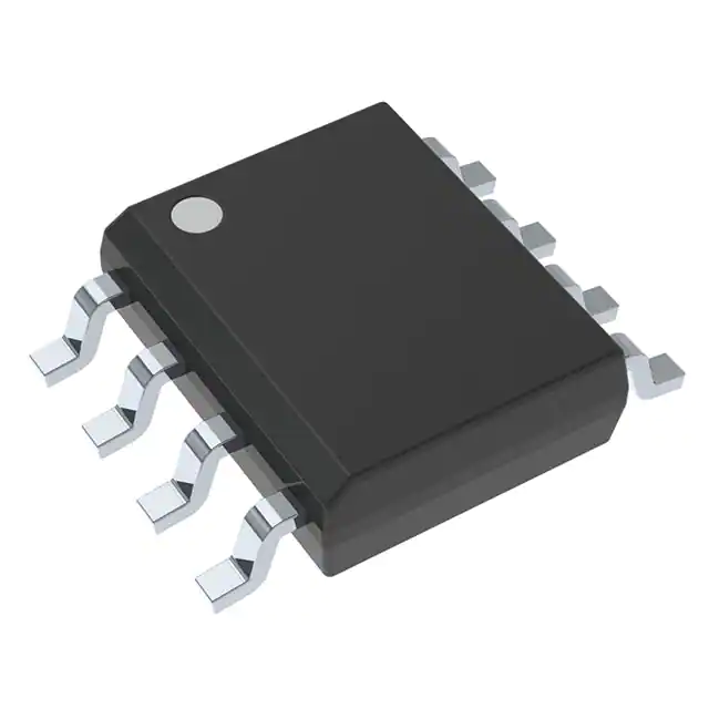
Semicon Original Variety Electronics Components Best STC AVR 8254 Microcontroller MCU IC TL2844BDR-8 SOP
The TL284xB and TL384xB series are pin compatible with the standard TL284x and TL384x with the following improvements. The start-up current is specified to be 0.5 mA (max), while the oscillator discharge current is trimmed to 8.3 mA (typ). In addition, during undervoltage lockout conditions, the output has a maximum saturation voltage of 1.2 V while sinking 10 mA (VCC = 5 V). Major differences between members of these series are the UVLO thresholds and maximum duty-cycle ranges. Typical UVLO thresholds of 16 V (on) and 10 V (off) on the TLx842B and TLx844B devices make them ideally suited to off-line applications. The corresponding typical thresholds for the TLx843B and TLx845B devices are 8.4 V (on) and 7.6 V (off). The TLx842B and TLx843B devices can operate to duty cycles approaching 100%. A duty-cycle range of 0% to 50% is obtained by the TLx844B and TLx845B by the addition of an internal toggle flip-flop, which blanks the output off every other clock cycle.The TL284xB-series devices are characterized for operation from –40°C to 85°C. The TL384xB-series devices are characterized for operation from 0°C to 70°C.
Product Attributes
|
TYPE |
DESCRIPTION |
|
Category |
Integrated Circuits (ICs) Interface - CODECs |
|
Mfr |
Texas Instruments |
|
Series |
- |
|
Package |
Tape & Reel (TR) Cut Tape (CT) Digi-Reel® |
|
SPQ |
250T&R |
|
Product Status |
Active |
|
Type |
Stereo Audio |
|
Data Interface |
PCM Audio Interface |
|
Resolution (Bits) |
24 b |
|
Number of ADCs / DACs |
2 / 2 |
|
Sigma Delta |
Yes |
|
S/N Ratio, ADCs / DACs (db) Typ |
92 / 102 |
|
Dynamic Range, ADCs / DACs (db) Typ |
93 / 97 |
|
Voltage - Supply, Analog |
2.7V ~ 3.6V |
|
Voltage - Supply, Digital |
1.65V ~ 1.95V |
|
Operating Temperature |
-40°C ~ 85°C |
|
Mounting Type |
Surface Mount |
|
Package / Case |
32-VFQFN Exposed Pad |
|
Supplier Device Package |
32-VQFN (5x5) |
|
Base Product Number |
TLV320 |
PWM controller
Pulse Width Modulation (PWM) refers to the use of the digital output of a microprocessor to control an analog circuit and is a method of digitally coding the level of an analog signal. Controlling analog circuits digitally can significantly reduce the cost and power consumption of a system. Many microcontrollers contain PWM controllers within them.
Principle
Brief description of the principle of the PWM controller
The basic principle of PWM control is based on the fact that narrow pulses of equal impulse volume and different shapes have the same effect when added to a link with inertia. There are various ways to classify pulse width modulation, such as unipolar and bipolar, synchronous and asynchronous, rectangular wave modulation, and sine wave modulation. The unipolar PWM control method means that the carrier wave is only transformed in one direction in half a cycle, and the PWM waveform is also only changed in one direction, while the bipolar PWM control method changes the carrier wave in two directions in half a cycle, and the PWM waveform is also changed in two directions. Depending on whether the carrier signal is synchronized with the modulating signal, PWM control can be divided into synchronous modulation and asynchronous modulation. Rectangular waveform pulse width modulation is characterized by the output pulse width column being equal width, and can only control a certain number of harmonics; Sine waveform pulse width modulation is characterized by the output pulse width column, not equal width, the width changes according to the sine rule, the output waveform is close to the sine waveform. Sine wave pulse width modulation is also called SPWM. generating the pulse width according to the control signal is the key to this technique. Triangular waveform comparison method, hysteresis loop comparison method, and space voltage vector method are commonly used.
PWM controllers
PWM controllers are well-known manufacturers.
The more famous ones are Texas Instruments, Motorola, Feifei Semiconductor, Unitrode, Micro Linear, Silicon General Semiconductor, Siemens, STMicroelectronics, and Royal Philips Semiconductors in the Netherlands, etc.
About Product
The TL284xB and TL384xB series of control integrated circuits provide the features that are necessary to implement off-line or dc-to-dc fixed-frequency current-mode control schemes, with a minimum number of external components. Internally implemented circuits include an undervoltage lockout (UVLO) and a precision reference that is trimmed for accuracy at the error amplifier input. Other internal circuits include logic to ensure latched operation, a pulse-width modulation (PWM) comparator that also provides current-limit control, and a totem-pole output stage designed to source or sink high-peak current. The output stage, suitable for driving N-channel MOSFETs, is low when it is in the off state.
The TL284xB and TL384xB series are pin compatible with the standard TL284x and TL384x with the following improvements. The start-up current is specified to be 0.5 mA (max), while the oscillator discharge current is trimmed to 8.3 mA (typ). In addition, during undervoltage lockout conditions, the output has a maximum saturation voltage of 1.2 V while sinking 10 mA (VCC = 5 V).
Major differences between members of these series are the UVLO thresholds and maximum duty-cycle ranges. Typical UVLO thresholds of 16 V (on) and 10 V (off) on the TLx842B and TLx844B devices make them ideally suited to off-line applications. The corresponding typical thresholds for the TLx843B and TLx845B devices are 8.4 V (on) and 7.6 V (off). The TLx842B and TLx843B devices can operate to duty cycles approaching 100%. A duty-cycle range of 0% to 50% is obtained by the TLx844B and TLx845B by the addition of an internal toggle flip-flop, which blanks the output off every other clock cycle.The TL284xB-series devices are characterized for operation from -40°C to 85°C. The TL384xB-series devices are characterized for operation from 0°C to 70°C.