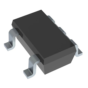
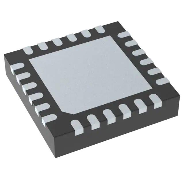
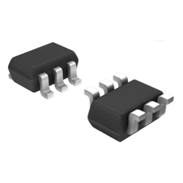
TPS62202DBVR – Integrated Circuits (ICs), Power Management (PMIC), Voltage Regulators – DC DC Switching Regulators
Product Attributes
| TYPE | DESCRIPTION |
| Category | Integrated Circuits (ICs)Power Management (PMIC)
Voltage Regulators - DC DC Switching Regulators |
| Mfr | Texas Instruments |
| Series | - |
| Package | Tape & Reel (TR)Cut Tape (CT)
Digi-Reel® |
| Product Status | Active |
| Function | Step-Down |
| Output Configuration | Positive |
| Topology | Buck |
| Output Type | Fixed |
| Number of Outputs | 1 |
| Voltage - Input (Min) | 2.5V |
| Voltage - Input (Max) | 6V |
| Voltage - Output (Min/Fixed) | 1.8V |
| Voltage - Output (Max) | - |
| Current - Output | 300mA |
| Frequency - Switching | 1MHz |
| Synchronous Rectifier | Yes |
| Operating Temperature | -40°C ~ 85°C (TA) |
| Mounting Type | Surface Mount |
| Package / Case | SC-74A, SOT-753 |
| Supplier Device Package | SOT-23-5 |
| Base Product Number | TPS62202 |
Documents & Media
| RESOURCE TYPE | LINK |
| Datasheets | TPS62200-05, TPS62207-08 |
| Design Resources | TPS62202 Design with WEBENCH® Power Designer |
| Featured Product | Create your power design now with TI’s WEBENCH® DesignerPower Management |
| PCN Assembly/Origin | Additional Assembly sites 21/Sep/2021 |
| EDA Models | TPS62202DBVR by SnapEDATPS62202DBVR by Ultra Librarian |
Environmental & Export Classifications
| ATTRIBUTE | DESCRIPTION |
| RoHS Status | ROHS3 Compliant |
| Moisture Sensitivity Level (MSL) | 1 (Unlimited) |
| REACH Status | REACH Unaffected |
| ECCN | EAR99 |
| HTSUS | 8542.39.0001 |
Construction of the voltage regulator
A typical switched-capacitor converter consists of four large MOS switches with a typical switching sequence of switching, doubling or halving the input supply voltage. The transfer and storage of energy is provided by external capacitors, the company cited with China's isolation transformer products in the market environment, production and operation, product import and export, industry investment environment and sustainable development of our country on the basis of this industry development trend to make a combination of qualitative and quantitative analysis and prediction. Engaged in transformers, voltage regulators, regulators and other low-voltage supporting products production, research and development, sales, "adhere to corporate innovation, the main products are: SBW high-power compensatory power regulator, SBW-F sub-regulated power regulator, SVC high-precision automatic AC regulator, precision purification regulator, microcomputer non-contact regulator, SG \ SBK isolation transformer, OSG\QZB autotransformer, ZSG\ZDG rectifier transformer, SSG servo transformer, DN resistance welding water-cooled transformer, reactor, contact autotransformer, column-type high-power electric regulator and other complete sets of electrical equipment. The products have novel design, small volume, beautiful shape, low loss, low noise, impact resistance and other advantages. Widely used in industrial and mining enterprises, textile machinery, printing and packaging, petrochemical industry, schools, shopping malls, lifts, post and telecommunications, medical machinery and all other occasions that require normal voltage assurance.
During the first part of the switching cycle, the input voltage is applied to a capacitor (C1). In the second part of the switching cycle, the charge is transferred from C1 to a second capacitor C2. The most conventional construction of switched-capacitor converters is a reversing converter, where C2 has a grounded positive terminal and its negative terminal passes a negative output voltage. After a few cycles, the voltage through C2 is applied to the input voltage. Assuming that there is no load on C2, no losses in the switch and no continuous resistance in the capacitor, the output voltage will be exactly the negative of the input voltage. In reality, the efficiency of the charge transfer (and consequently the accuracy of the output voltage) depends on the switching frequency, the resistance of the switch, the value of the capacitor and the continuity resistance. A similar topology doubler uses the same switch and capacitor bank, but changes the ground connection and input voltage. Other more complex variants use additional switches and capacitors to achieve other transformation ratios of input to output voltage and, in some cases, specialised switching sequences to produce fractional relationships. In their simplest form, switched capacitor converters are not voltage regulated. Some of the new National Semiconductor switched-capacitor converters have automatically adjustable gain levels to produce a regulated output; other switched-capacitor converters use an internal low dropout linear regulator to produce an unregulated output.


