


Electronics Component Original IC LC898201TA-NH
Product Attributes
| TYPE | DESCRIPTION |
| Category | Integrated Circuits (ICs)PMIC - Motor Drivers, Controllers |
| Mfr | onsemi |
| Series | - |
| Package | Tape & Reel (TR) |
| Product Status | Active |
| Motor Type - Stepper | Bipolar |
| Motor Type - AC, DC | Brushed DC, Voice Coil Motor |
| Function | Driver - Fully Integrated, Control and Power Stage |
| Output Configuration | Half Bridge (14) |
| Interface | SPI |
| Technology | CMOS |
| Step Resolution | - |
| Applications | Camera |
| Current - Output | 200mA, 300mA |
| Voltage - Supply | 2.7V ~ 3.6V |
| Voltage - Load | 2.7V ~ 5.5V |
| Operating Temperature | -20°C ~ 85°C (TA) |
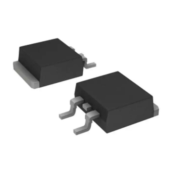
| Mounting Type | Surface Mount |
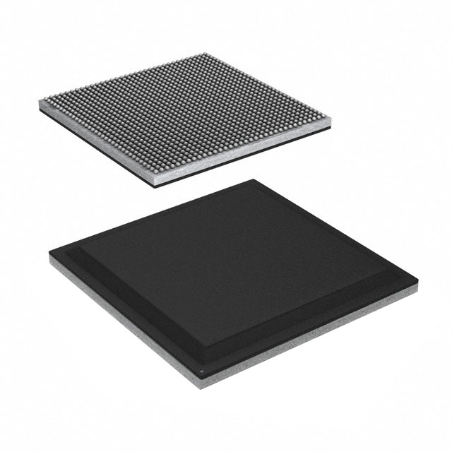
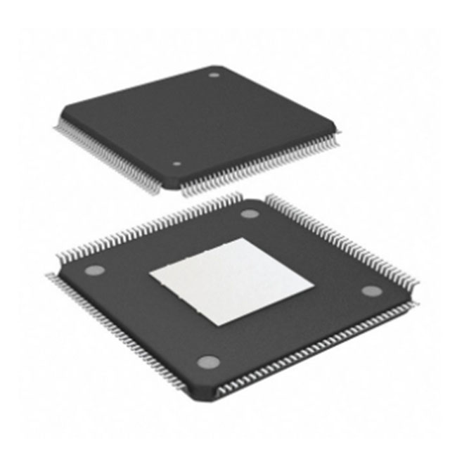
| Package / Case | 64-TQFP |
| Supplier Device Package | 64-TQFP (7x7) |
| Base Product Number | LC898201 |
| SPQ | 1000/pcs |
Introduction
The motor driver is a switch, because the motor drive current is very large or the voltage is very high, and the general switch or electronic components cannot be used as a switch to control the motor.
The role of the motor driver: The role of the motor driver refers to the way to achieve the control of the motor idle speed by controlling the rotation angle and operating speed of the motor, so as to achieve the control of the duty cycle.
Motor drive circuit schematic circuit diagram: The motor drive circuit can be driven either by relay or power transistor, or by using a thyristor or a power MOS FET. In order to adapt to different control requirements (such as the working current and voltage of the motor, the speed regulation of the motor, the forward and reverse control of the DC motor, etc.), different types of motor drive circuits must meet the relevant requirements.
The electric vehicle does not start when it is energized, and it is more laborious to push and accompanied by a "choking" sound. This situation is that the motor cable is short-circuited due to contact with the virtual connection, and the phenomenon of pushing the cart with three thick phase lines of the motor can be unplugged and disappears, indicating that the controller is broken and needs to be replaced in time. If it is still difficult to implement, it means that there is a problem with the motor, and it may be caused by the short circuit of the motor coil being burned out.
Features
Built-in equalizer circuit by digital operation
- Iris control equalizer circuit
- Focus control equalizer circuit (MR sensor can be connected.)
- Coefficients can be set arbitrarily through the SPI interface.
- Computed values in the equalizer can be monitored.
Built-in 3ch stepping motor control circuits
SPI bus interface
PI control circuit
- 30mA Sink output terminal
- Built-in PI detecting function (A/D method)
A/D converter
- 12bit (6ch)
: Iris, Focus, PI detection, General
D/A converter
- 8bit (4ch)
: Hall offset, Constant current bias, MR Sensor offset
Operation Amplifier
- 3ch (Iris control x1, Focus control x2)
PWM pulse generator
- PWM Pulse generator for feedback control (Up to 12bit accuracy)
- PWM pulse generator for stepper motor control (Up to 1024 micro steps)
- PWM pulse generator for general-purpose H-Bridge (128 voltage levels)
Motor Driver
- ch1 to ch6: Io max=200mA
- ch7: Io max=300mA
- Built-in thermal protection circuit
- Built-in low-voltage malfunction prevention circuit
Selective usage either internal OSC (Typ. 48MHz) or external oscillating circuit(48MHz)
Power supply voltage
- Logic unit: 2.7V to 3.6V (IO, Internal core)
- Driver unit: 2.7V to 5.5V (Motor drive)
-
Quote BOM List IC IDW30C65D2 GSD4E-9333-TR EP1A...
-
New In Stock Integrated Circuit TLE4250-2G IRF7...
-
Selling Well Integrated Circuit HFBR-772BWZ In ...
-
Electronic Components IC Chips Integrated Circu...
-
IRF4905STRLPBF New & Original Electronic C...
-
Electronic Components 10CL010YE144I7G Original ...