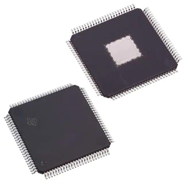
Logic & Flip Flops-SN74LVC74APWR
Product Attributes
|
Documents & Media
| RESOURCE TYPE | LINK |
| Datasheets | SN54LVC74A, SN74LVC74A |
| Featured Product | Analog Solutions |
| PCN Packaging | Reel 10/Jul/2018 |
| HTML Datasheet | SN54LVC74A, SN74LVC74A |
| EDA Models | SN74LVC74APWR by SnapEDA |
Environmental & Export Classifications
| ATTRIBUTE | DESCRIPTION |
| RoHS Status | ROHS3 Compliant |
| Moisture Sensitivity Level (MSL) | 1 (Unlimited) |
| REACH Status | REACH Unaffected |
| ECCN | EAR99 |
| HTSUS | 8542.39.0001 |
Flip-Flop and Latch
Flip-Flop and Latch are common digital electronic devices with two stable states that can b e used to store information, and one flip-flop or latch can store 1 bit of information.
Flip-Flop (Abbreviated as FF), also known as a bistable gate, also known as a bistable flip-flop, is a digital logic circuit that can operate in two states. Flip-flops remain in their state until they receive an input pulse, also known as a trigger. When an input pulse is received, the flip-flop output changes state according to the rules and then remains in that state until another trigger is received.
Latch, sensitive to the pulse level, changes state under the level of the clock pulse, latch is a level-triggered storage unit, and the action of data storage depends on the level value of the input signal, only when the latch is in the enable state, the output will change with the data input. Latch is different from flip-flop, it is not latching data, the signal at the output changes with the input signal, just like the signal passing through a buffer; once the latch signal acts as a latch, the data is locked and the input signal does not work. A latch is also called a transparent latch, which means that the output is transparent to the input when it is not latched.
The difference between latch and flip-flop
Latch and flip-flop are binary storage devices with memory function, which are one of the basic devices to compose various timing logic circuits. The difference is: latch is related to all its input signals, when the input signal changes latch changes, there is no clock terminal; flip-flop is controlled by the clock, only when the clock is triggered to sample the current input, generate the output. Of course, because both latch and flip-flop are timing logic, the output is not only related to the current input, but also related to the previous output.
1. latch is triggered by level, not synchronous control. DFF is triggered by clock edge and synchronous control.
2、latch is sensitive to the input level and is affected by the wiring delay, so it is difficult to ensure that the output does not produce burrs; DFF is less likely to produce burrs.
3, If you use gate circuits to build latch and DFF, latch consumes less gate resources than DFF, which is a superior place for latch than DFF. Therefore, the integration of using latch in ASIC is higher than DFF, but the opposite is true in FPGA, because there is no standard latch unit in FPGA, but there is DFF unit, and a LATCH needs more than one LE to be realized. latch is level triggered, which is equivalent to having an enable end, and after activation (at the time of enable level) is equivalent to a wire, which changes with The output varies with the output. In the non-enabled state is to maintain the original signal, which can be seen and flip-flop difference, in fact, many times latch is not a substitute for ff.
4, latch will become extremely complex static timing analysis.
5, at present, latch is only used in the very high-end circuit, such as intel's P4 CPU. FPGA has latch unit, the register unit can be configured as a latch unit, in xilinx v2p manual will be configured as register/latch unit, the attachment is xilinx half slice structure diagram. Other models and manufacturers of FPGAs did not go to check. --Personally, I think xilinx is able to directly match the altera may be more trouble, to a few LE to do, however, not xilinx device each slice can be so configured, altera's only DDR interface has a special latch unit, generally only high-speed circuit will be used in the latch design. altera's LE is no latch structure, and check the sp3 and sp2e, and other not to check, the manual says that this configuration is supported. The expression wangdian about altera is right, altera's ff can not be configured to latch, it uses a lookup table to implement latch.
The general design rule is: avoid latch in most designs. it will let you design the timing is finished, and it is very hidden, non-veteran can not find. latch the biggest danger is not to filter burrs. This is extremely dangerous for the next level of the circuit. Therefore, as long as you can use D flip-flop place, do not use latch.
.png)